
Keep Your Piles on Point with Precise Installation Tolerances


Keep Helical Piles on Point From the First Turn
A sound helical pile installation tolerance starts with three checks: location, alignment, and final elevation. A common project specification allows a pile to be within 3 inches of its planned location, within about 2 to 3 degrees of its intended angle, and at the approved cut-off elevation. If a pile exceeds the allowed plumb limit - often 2% of pile length under older regional pile provisions - the engineer should review the added lateral and bending forces before the foundation is accepted.
For waterfront property owners in Nassau and Suffolk Counties, this matters because a pile that is only slightly misplaced can create eccentric loading at a pile cap, bulkhead support, dock framing connection, pier support, or grade beam. The fix is not always removal and replacement, but it always requires documentation and engineering review tied to the marine structure being built or repaired.
Pearce Marine Construction is a woman-owned marine construction company serving residential, commercial, and public clients across Nassau and Suffolk Counties on Long Island, NY. For shoreline structures in Southampton, West Islip, West Hampton, and nearby Long Island waterfront communities, precise layout, torque monitoring, and as-built records help ensure the finished foundation supports the structure as designed.

For related marine foundation planning:
- Pearce Marine provides certified helical pile installers for dock, pier, bulkhead, and shoreline support work.
- Specialized helical pile installation equipment helps control torque, alignment, and embedment on marine sites.
- Understanding helical pile installation time helps owners plan waterfront construction schedules.
Code Standards and Helical Pile Installation Tolerance Limits

Deep foundation engineering relies on stringent regulatory benchmarks to maintain load transfer safety. When engineering helical foundations for coastal bulkheads, seawalls, docks, retaining walls, walkways, or anchoring systems for marine structures, building codes establish baseline limits that prevent structural failures. The International Building Code (IBC Section 1810) and regional provisions govern deep foundations, demanding strict verification of load capacities and geometrical accuracy.
Industry-standard construction divisions, such as SECTION 31 66 13 HELICAL PILES AND HELICAL ANCHORS, lay out prescriptive thresholds that ensure every installed element behaves according to design calculations. Manufacturers and structural engineers rely on published engineering reference manuals to establish working criteria for rotational speed, alignment, and axial deviation during advancement.
Core Helical Pile Installation Tolerance Guidelines for Plumb, Position, and Elevation
Maintaining dimensional precision in the field requires tracking several distinct geometrical parameters:
- Plan Location (Horizontal Deviation): Standard specifications allow a horizontal placement tolerance of ±3 inches (75 mm) from the designed coordinate grid. Staying within this window ensures that downward loads transfer directly into the pile shaft without overstressing foundation brackets or pile caps.
- Plumbness and Angular Alignment: Piles must not deviate more than ±2° to 3° from the designated installation angle (whether vertical or battered). Regional building codes stipulate that if a pile's axis drifts out of plumb by more than 2% of the total embedded pile length, the foundation design must be evaluated and modified for the resulting eccentric forces. Pearce Marine uses these criteria during marine pile layout and alignment; see the helical pile installation guide for related waterfront installation methods.
- Elevation and Cut-off: Final top-of-shaft cut-off elevation typically holds a tight tolerance of ±1/4 inch for direct framing connections, or up to ±2 inches when embedded in cast-in-place concrete pile caps.
- Coupling Fit-Up: Axial clearance between modular shaft sections and coupling sleeves is restricted to 1/16 inch or less, ensuring direct steel-on-steel axial contact without relying on coupling cross-bolts for load bearing. Bolt-hole elongation caused by rotational torsion during advancement must never exceed 1/4 inch.
Comparative Analysis: Helical Pile Tolerances Across Installation Conditions
Helical piles provide precise geometric control compared to conventional impact-driven deep foundation systems. Because torque motors rotate the shaft continuously rather than slamming it downward with impact hammers, an experienced operator can make immediate micro-adjustments to maintain plumbness.
| Foundation Type / Application | Positional Tolerance (Plan) | Angular / Plumbness Tolerance | Elevation / Cut-Off Tolerance | Primary Governing Factors |
|---|---|---|---|---|
| Helical Piles (Compression / Tension) | ±3 inches (75 mm) | ±2° to 3° (Max 2% of pile length) | ±1/4" to ±2" depending on cap | Hydraulic crowd, continuous rotation |
| Driven Timber / Steel Piles | ±3 inches (75 mm) | Max 1 in 75 (~1.33% slope / ~0.75°) | ±1 inch to ±2 inches | Hammer alignment, soil refusal |
| Steel Sheet Pile Walls | ±50 mm (normal to wall line) | ±1% driven depth (normal to line) | ±20 mm top / ±120 mm toe | Interlock friction, guide templates |
| Helical Anchors (Battered Tiebacks) | ±3 inches at entry point | ±2° along specified batter angle | Verified by bracket position | Angle template, anchor alignment |
Our custom marine operations also incorporate heavy-duty pile driving when required by dense underlying strata or specific engineering criteria.
Structural Consequences of Exceeding Helical Pile Installation Tolerance
Allowing a helical pile to stray beyond approved limits introduces unintended physical stresses into both the pile shaft and the supported marine structure.

When axial loads are applied off-center, secondary bending moments develop along the unbraced length of the pile shaft. This creates P-Delta effects—where lateral deflection amplifies internal bending moments, reducing the ultimate compression capacity of the foundation. Hollow round shafts handle these combined stresses better than slender square bars, but severe out-of-plumb angles can lead to localized shaft buckling near the soil surface. Furthermore, excessive angular tilt can cause the helix plates to bear unevenly on stratified soil layers, diminishing end-bearing efficiency and leading to differential settlement under marine decking or dock structures.
How to Maintain and Verify Tolerances in the Field
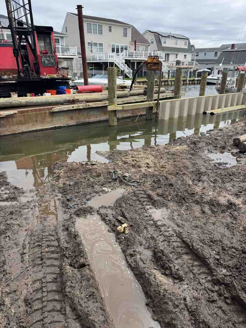
Achieving tight tolerances demands professional-grade machinery, calibrated hydraulic drive heads, and constant oversight. Drive heads should operate between 5 and 20 RPM to ensure smooth soil cutting without augering or churning the ground. The operator must match downward crowd force directly to the lead section's helix pitch—typically 3 inches per revolution (advancing at 80% to 100% of theoretical pitch per turn).
Professional Field Measurement and Alignment Verification
Maintaining strict installation accuracy requires continuous monitoring across every phase of marine construction:
- Pre-Installation Staking and Baseline Survey: Survey crews stake all pile coordinates using optical total stations or high-precision RTK GPS units, referencing established benchmarks along the waterfront property.
- Initial Plumb Setup: Before the drive head engages full rotation, the lead section is aligned vertically or set to the specified batter angle using magnetic dual-axis digital inclinometers attached directly to the shaft.
- Continuous Alignment Monitoring: As the lead section penetrates the upper soils, a spotter verifies alignment from two orthogonal directions using digital torpedo levels or optical sighting tools, making instantaneous boom corrections.
- Extension Tracking: When coupling additional extensions, fit-up tolerances (≤ 1/16 inch) are checked, and angular tracking continues at 3-foot embedment intervals.
- Final Elevation Verification: Optical or rotating laser levels confirm that the final cut-off elevation matches structural engineering drawings for dock girders, bulkhead whalers, pier framing, or foundation brackets. Our helical piles crews use these checks for waterfront foundations throughout Nassau and Suffolk Counties.
Torque-to-Capacity Quality Control and Handling Refusal
One of the greatest engineering strengths of helical foundation systems is the empirical torque-to-capacity relationship:
Qu = Kt × T
Where Qu is the ultimate geotechnical capacity, Kt is the empirical torque correlation factor (ranging from roughly 3 to 10 ft⁻¹ depending on shaft diameter and geometry), and T is the final effective installation torque. To verify capacity, torque indicators must be calibrated annually and read at 1-foot intervals across the final 3 feet of penetration. Technical specifications such as CHANCE® Helical Piles documentation establish explicit torque limits for specific steel shafts.

When subterranean obstructions such as glacial erratics, cobbles, or buried timber are struck:
- Never Over-Torque: Never exceed the manufacturer's maximum torsional strength rating for the shaft type.
- Spin-Out Prevention: If the pile spins without advancing at least 80% of its pitch, stop immediately to prevent soil churning and loss of lateral support.
- Backing Out and Pre-Drilling: Back the pile out 1 to 2 feet and re-advance with adjusted crowd force. If refusal persists, extract the pile, drill a small pilot hole to displace the obstruction, or have Pearce Marine evaluate the soil mechanics described in our helix pile technical reference.
Corrective Actions, Engineering Redesigns, and As-Built Records
If a helical pile exceeds installation tolerances due to underground obstructions or shifting soils, standardized remediation protocols allow the marine foundation to meet structural safety standards:
- Supplemental Pile Additions: Install an adjacent "sister" pile spaced at least three times the largest helix diameter away (typically 3 to 5 feet) and tie the two elements together with an enlarged structural cap.
- Foundation Grade Beam and Bracket Redesign: Structural engineers can adjust grade beam reinforcement, widen concrete caps, or utilize custom engineered steel retrofit brackets to bridge positional offsets.
- Static Proof Load Testing: Perform an on-site static compressive or tensile proof load test per ASTM D1143 / D3689 to verify that the pile achieves its required factor of safety (minimum 2.0) despite positional deviations.
- As-Built Documentation and Special Inspection Records: Certified special inspectors log final depth, effective torque, angular deviation, and plan coordinates for the completed dock, pier, bulkhead, seawall, retaining wall, or anchoring system.
Whether executing complex bulkhead anchoring in Southampton, custom dock foundation piling in West Islip, or robust shoreline stabilization in West Hampton, Pearce Marine Construction delivers uncompromising precision. Waterfront property owners choose Pearce Marine over competitors like Bayview Dockbuilders and Kevel because our deep local expertise, specialized equipment, and superior craftsmanship ensure your marine foundation remains secure for decades. As a woman-owned marine construction company serving residential, commercial, and public clients across Nassau and Suffolk Counties, our generational knowledge and exacting standards protect your waterfront investment.



Bring Your Vision to Life
Whether you're planning a custom dock, seawall, or boat lift, our experienced team is ready to deliver high-quality marine construction tailored to your needs. Pearce Marine Construction brings craftsmanship, precision, and a deep understanding of Florida’s waterways to every project. Let us help you create a durable, beautiful solution that stands the test of time. Get in touch now for a personalized estimate!