
Helical Pile Installation Torque Demystified for Marine and Land Projects

Why Helical Pile Installation Torque Matters for Waterfront Foundations
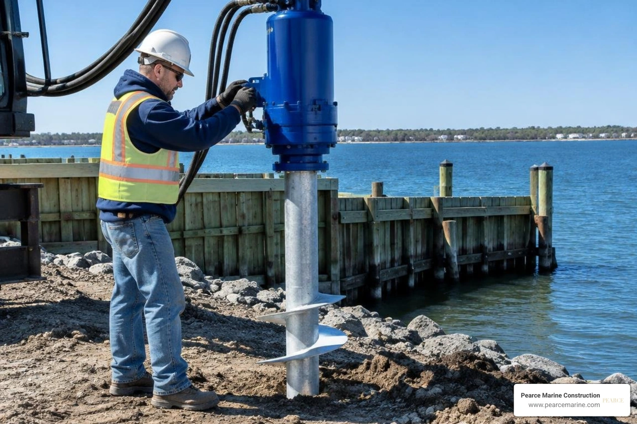
Helical pile installation torque is the rotational force needed to screw a pile into the ground. For a dock, bulkhead, deck, or shoreline structure, the torque recorded near final depth is a key field check of whether the pile has likely reached its designed axial capacity.
A qualified installer should:
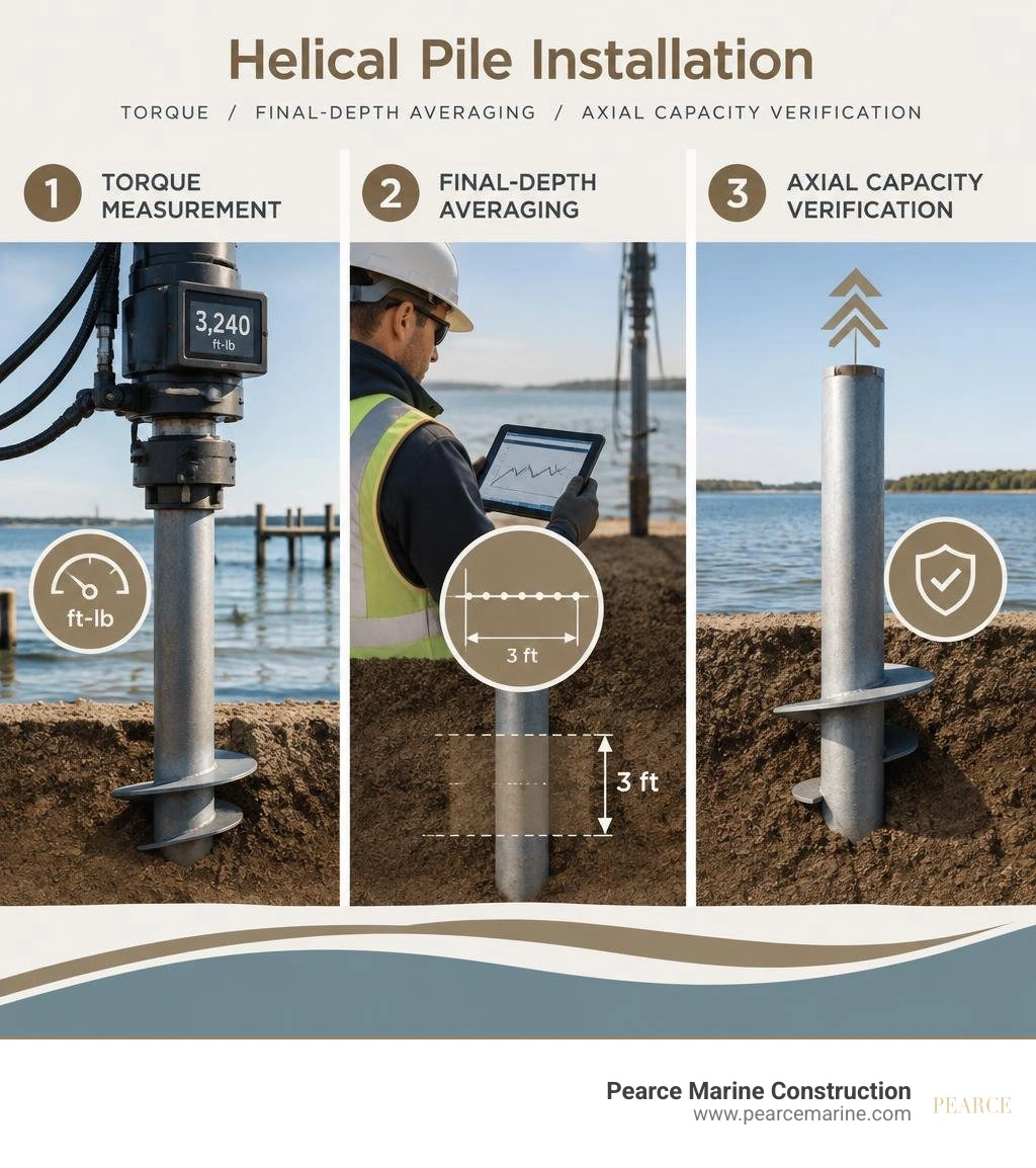
- Set a project-specific target torque from the engineered load and soil conditions.
- Measure torque with a calibrated in-line or digital monitoring device throughout installation.
- Keep the pile advancing close to one helix pitch per revolution, rather than spinning in place.
- Average readings over the final 3 feet of installation and confirm that torque meets the specified minimum without exceeding the pile shaft's torque rating.
Higher torque often signals stronger soil resistance and greater potential capacity, but it is not a stand-alone guarantee. Helix size, shaft diameter, soil type, depth, installation rate, and applied downforce all affect the result. This matters especially along Nassau and Suffolk County shorelines, where soft or sensitive marine soils can change sharply over short distances.
For dependable waterfront work, torque records should be paired with the geotechnical design, correct pile geometry, final depth, and load-testing requirements. Pearce Marine Construction provides this level of controlled installation for residential, commercial, and public marine projects across Long Island. Explore our detailed resources for choosing qualified helical pile installation contractors, inspecting specialized helical pile installation equipment, and budgeting commercial or residential helical pile installation costs.
Understanding Helical Pile Installation Torque and Load Capacity Correlation
How Helical Pile Installation Torque Predicts Ultimate Axial Capacity
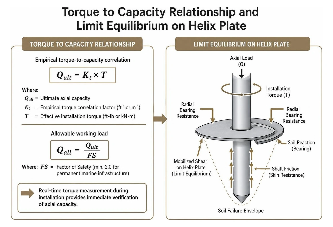
The core principle behind helical deep foundations is the direct, empirical relationship between rotational driving resistance and ultimate axial load capacity. As a helical pile rotates into subsurface strata, the resistance encountered by the steel helix plates and central shaft directly reflects the shearing resistance of the surrounding soil.
Geotechnical engineers calculate this using the empirical torque-to-capacity correlation pioneered by Hoyt and Clemence:
$$Q_{ult} = K_t \times T$$
Where:
- $Q_{ult}$ is the ultimate axial capacity (in compression or tension/uplift).
- $K_t$ is the empirical torque correlation factor (measured in $\text{ft}^{-1}$ or $\text{m}^{-1}$).
- $T$ is the effective installation torque achieved during penetration (in $\text{ft-lb}$ or $\text{kN}\cdot\text{m}$).
The torque correlation factor ($Kt$) is governed primarily by the central shaft geometry and dimensions, though soil conditions and plate layout also influence the result. For standard round pipe shafts and solid square shafts, pre-qualified $Kt$ values range between $3\text{ ft}^{-1}$ and $10\text{ ft}^{-1}$ ($10\text{ to }33\text{ m}^{-1}$). To establish the allowable working load limit ($Q_{all}$), engineering standards apply a minimum factor of safety ($FS$), typically $FS = 2.0$ for permanent marine infrastructure:
$$Q_{all} = \frac{Q_{ult}}{FS}$$
In classical geotechnical design, axial capacity is also calculated independently using the individual plate bearing method derived from Terzaghi's bearing capacity theory. Modern research on analytical installation models demonstrates that physical equilibrium equations can evaluate how limit-equilibrium soil envelopes generate rotational friction on the helix surfaces and central shaft.
Having real-time torque correlation during installation gives marine contractors an immediate, verifiable check on bearing strata, ensuring deep foundations for heavy boardwalks, seawalls, and dock structures meet rigorous engineering standards. For a complete look at equipment and load requirements, review our specialized helical piles complete guide.
Geotechnical and Geometric Factors Affecting Helical Pile Installation Torque
Installation torque is not solely determined by soil density; it is heavily influenced by geometric configuration, mechanical equipment settings, and geotechnical stratigraphy.
1. Helix Plate Geometry and Layout
The diameter, count, and spacing of the bearing plates alter rotational drag. Research shows that increasing the primary helix diameter by 50% can more than double the required drive torque due to the exponential increase in plate surface area and soil displacement. True-pitch helical plates—formed with matched metal dies—minimize soil disturbance, preserving intact shear strength so the calculated $K_t$ remains accurate. Multi-helix configurations must maintain an inter-helix spacing of at least three times the lower helix diameter to ensure each plate acts as an independent bearing element without overlapping shear zones.
2. Shaft Geometry (Round Pipe vs. Solid Square)
Solid square shafts (e.g., Type SS) present a compact cross-section that displaces minimal soil, resulting in high torque correlation factors ($Kt \approx 10\text{ ft}^{-1}$). Large-diameter round pipe shafts (e.g., Type RS) provide exceptional lateral stability and buckling resistance for unsupported water columns, but generate substantial side friction. Because shaft skin resistance absorbs a portion of the rotational energy without directly adding proportional end-bearing capacity, larger round shafts yield lower correlation factors ($Kt \approx 3\text{ to }9\text{ ft}^{-1}$).
3. Soil Mechanics: Sand vs. Cohesive Clay
- Cohesionless Soils (Sands and Gravels): Torque is governed by internal friction angle ($\phi$), relative density, and effective overburden stress. Piles installed into dense coastal sands encounter rapid torque spikes, requiring substantial hydraulic drive power.
- Cohesive Soils (Clays and Silts): Rotational resistance is determined by undrained shear strength ($s_u$) and soil sensitivity. In sensitive marine clays common along Long Island harbors, disturbance can temporarily reduce shear strength, requiring extension deep into dense glacial till or sand layers.
4. Shaft Adhesion and Axial Crowd Force
Shaft skin resistance and shear stresses along the steel perimeter contribute substantially to total driving torque. In deep installations, shaft resistance can account for 30% to 45% of total recorded torque. Additionally, applied crowd (downward axial thrust) must be carefully controlled; excessive crowd force artificially depresses recorded torque while shearing the soil, whereas inadequate downforce leads to pile spin without advancement.
An academic study on torque-to-capacity relationships emphasizes that $K_t$ values must account for soil stratification, installation rate, and shaft interface mechanics rather than relying strictly on nominal catalog values.
| Shaft Type & Size | Shaft Profile | Typical $K_t$ Factor ($\text{ft}^{-1}$) | Primary Soil Strata Suitability | Common Marine Construction Application |
|---|---|---|---|---|
| SS5 / SS150 (1.50" - 1.75") | Solid Square RCS | $10$ | Dense Sand, Stiff Clay, Hardpan | Bulkhead tieback anchors, tension anchors |
| RS2875 (2.875" OD) | Round Pipe | $9$ | Medium Sand, Silt, Layered Clay | Residential piers, lightweight walkways |
| RS3500 (3.500" OD) | Round Pipe | $7$ | Coastal Sands, Marine Silt | Custom waterfront decks, fixed docks |
| RS4500 (4.500" OD) | Round Pipe | $6$ | Deep Soft Clay over Glacial Till | Heavy commercial docks, seawall foundations |
| Pipe Shaft ($\ge 8.625"$) | Large Pipe | $3 - 4$ | Variable Marine Sediments | Heavy marine moorings, high-lateral piers |
Field Measurement, Quality Control, and Deep Foundation Execution
Real-Time Torque Monitoring and Neutral Rotation Rate Standards
Achieving designed structural capacity requires continuous torque monitoring during pile advancement.
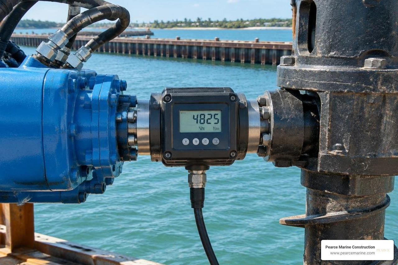
Industry best practices rely on calibrated in-line digital torque transducers (such as wireless drive sensors or load-cell torque pins) mounted directly between the hydraulic drive motor and the pile drive tool. While hydraulic differential pressure gauges provide a general estimate, direct in-line sensors eliminate errors caused by hydraulic fluid temperature, line loss, motor wear, and backpressure variations.
To maintain structural integrity and comply with ICC-ES AC358 standards, our marine crews adhere to strict rotational operating parameters:
- Controlled Rotational Speed: Drive heads must operate at low speeds—typically between 5 and 20 RPM, never exceeding 25 RPM. Rapid rotation churns and remolds the soil, destroying the natural soil matrix and reducing load capacity.
- Neutral Rotation and Penetration Pitch Rate: Piles must advance smoothly into the ground at a rate matching the pitch of the helix plates—typically 2.5 to 3.0 inches per revolution (a minimum advancement rate of 85% to 100% of theoretical pitch). If a pile rotates without advancing, it augers the soil, drastically degrading both immediate torque readings and long-term axial capacity.
- Effective Torque Averaging: In multi-helix and single-helix tension systems, the design torque must be verified by calculating the average torque recorded across the final 3 feet of penetration, logged at 1-foot increments.
For an in-depth breakdown of hydraulic drive systems, view our comprehensive helical pile installation guide.
Verification Protocols for Coastal and Marine Deep Foundations
Marine foundation installations in tidal and nearshore environments present unique geotechnical challenges that demand thorough quality control protocols.
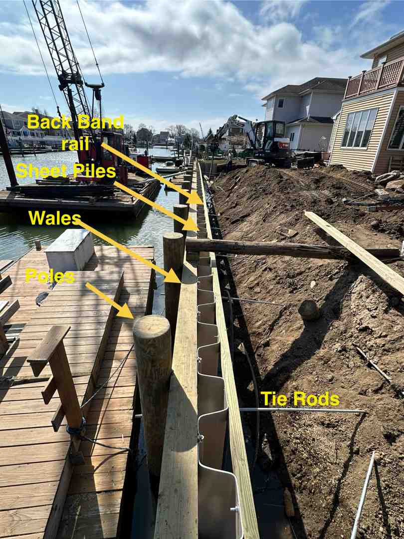
When driving deep foundations across coastal zones like Southampton, West Islip, Wantagh, Massapequa, Babylon, and Cold Spring Harbor, subsurface profiles frequently transition from loose, organic tidal silt to dense glacial outwash gravels. Foundation verification involves the following procedures:
- Torque vs. Depth Verification: Piles must achieve both the minimum engineered embedment depth (to prevent shallow failure, frost heave, or scour undermining) and the minimum effective installation torque. If target torque is reached before design depth due to an isolated boulder or lens, pre-drilling or pile relocation may be required.
- Plain Extension Sequencing: If a pile reaches the planned depth without achieving target torque, solid or pipe plain extensions are coupled using high-strength structural bolts torqued to snug-tight conditions (per AISC 360). Installation continues until the helices penetrate competent load-bearing strata.
- Torque Rating Thresholds: Torque must never exceed the mechanical manufacturing rating of the shaft (for example, 5,700 ft-lb for Type SS5, or 25,000 ft-lb for Type RS4500). Applying torque beyond these limits risks torsional shear failure or pin-hole deformation.
- Accounting for Marine Soil Sensitivity: In sensitive coastal clays, dynamic disturbance can cause temporary strength loss. Installers must account for setup effects, verify torque in dense sub-layers, and perform static axial proof-load testing when specified.
As a woman-owned marine construction company serving residential, commercial, and public clients across Nassau and Suffolk Counties on Long Island, NY, Pearce Marine Construction brings generational expertise and technical precision to every shoreline project. Whether constructing bulkheads in Southampton and West Islip, building deep-water piers in Huntington, or anchoring retaining walls in Lloyd Harbor, our crews utilize calibrated torque-monitoring systems to deliver fully verified deep foundations. Waterfront property owners and municipal engineers choose Pearce Marine Construction over competitors like Bayview Dockbuilders and Kevel for our superior craftsmanship, local coastal knowledge, meticulous engineering adherence, and specialized marine equipment that guarantee lasting foundation stability.
To discuss engineering specifications or schedule deep foundation work for your waterfront project, contact our team for specialized helical pile services.
Frequently Asked Questions
What is the capacity-to-torque ratio ($K_t$) and how is it used?
The capacity-to-torque ratio ($Kt$) is an empirical factor that correlates installation torque to ultimate axial load capacity ($Q{ult} = K_t \times T$). Ranging from $3\text{ ft}^{-1}$ to $10\text{ ft}^{-1}$, it allows engineers to confirm that a pile can safely support structural loads by calculating its holding capacity directly from driving torque measured in the field.
What should be done if target torque is not reached at design depth?
If the pile reaches its estimated depth without developing the required torque, the soil at that layer lacks adequate shear strength. Installers add plain steel extensions to drive the helix plates deeper into competent load-bearing strata until the averaged torque over the final 3 feet satisfies the design requirement.
Why is advancing at one pitch per revolution critical?
Advancing at approximately one helix pitch per rotation (2.5 to 3.0 inches per revolution) ensures the plates cut smoothly through the soil with minimal disturbance. If rotation occurs without forward movement, the plates auger and compromise the soil, significantly reducing bearing capacity.
How does Pearce Marine Construction ensure torque accuracy on Long Island?
We utilize calibrated in-line digital torque indicators rather than relying solely on hydraulic pressure gauges. Our teams maintain detailed installation logs recording depth, torque at 1-foot intervals, and advance rates for every pile driven across Nassau and Suffolk Counties.



Bring Your Vision to Life
Whether you're planning a custom dock, seawall, or boat lift, our experienced team is ready to deliver high-quality marine construction tailored to your needs. Pearce Marine Construction brings craftsmanship, precision, and a deep understanding of Florida’s waterways to every project. Let us help you create a durable, beautiful solution that stands the test of time. Get in touch now for a personalized estimate!