
Step-by-Step Guide to Interlocking Brick Wall Construction

Why Professional Interlocking Brick Wall Construction Matters
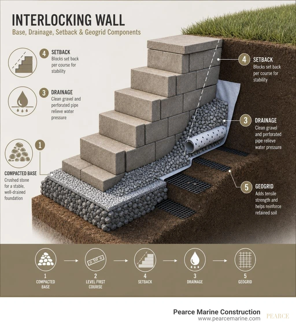
Interlocking brick wall construction uses precision-made blocks that lock together with lips, pins, or tongue-and-groove connections. For a retaining wall, the critical work is not simply stacking blocks: it is preparing a compacted crushed-stone base, leveling the first course, building in proper setback, installing drainage behind the wall, and adding engineered geogrid where site loads or wall height require it.
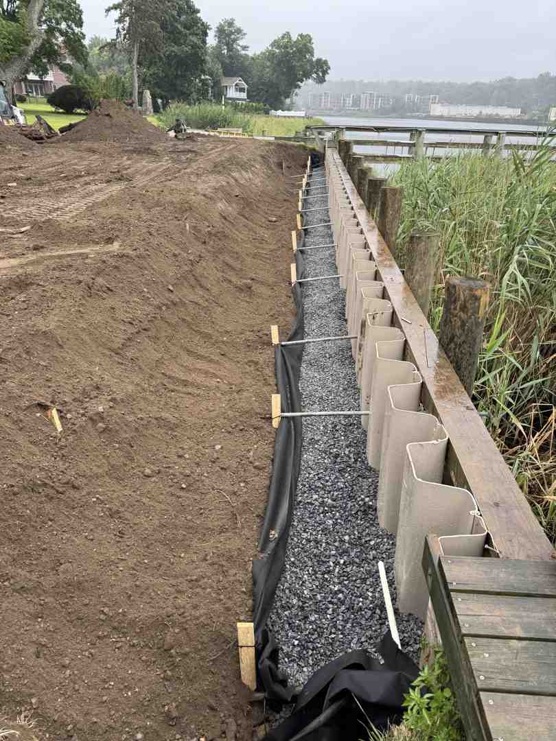
This system can provide a durable, flexible alternative to mortared masonry or poured concrete. But on waterfront and coastal properties, drainage, soil conditions, scour risk, and structural load demands can determine whether a wall stays straight or begins to lean, bulge, or settle.
For properties in Nassau and Suffolk Counties, Pearce Marine Construction evaluates the full shoreline condition before recommending an interlocking retaining system. As a woman-owned marine construction company serving residential, commercial, and public clients across Long Island, we build walls designed around the site's soil, water movement, grades, and required structural support.
Quick look at interlocking brick wall construction:
- constructing a retaining wall with blocks
- retaining wall construction materials
- retaining wall construction
Structural Standards for Interlocking Retaining Systems
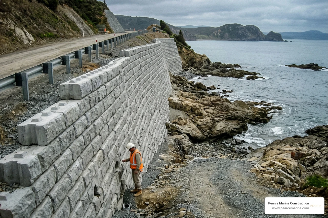
Dry-stack mechanics rely on the physical mass of individual units combined with integrated shear keys, rear lips, or polymer pin systems. Unlike rigid mortared masonry, mortarless interlocking systems eliminate joint cracking caused by lateral earth pressure and seasonal freeze-thaw cycles. Manufactured units frequently achieve compressive strengths exceeding 3,000 to 5,000 PSI with low absorption rates (5% to 9%), delivering robust resistance against saturated coastal conditions.
The primary engineering objective of an interlocking earth retention system is mitigating hydrostatic pressure while distributing active lateral soil loads across an integrated mass. By using specialized shear connectors or offset tongue-and-groove channels, the structure channels lateral forces downward into a prepared gravel foundation footing.

Engineering Foundations and Soil Mechanics
Proper design begins with an analysis of the retained soil’s internal angle of friction, cohesion, and moisture sensitivity. Highly plastic soils or saturated clays exert immense active lateral pressure, demanding wider excavation profiles and enhanced aggregate backfill zones.
Segmental retaining wall units manufactured under ASTM C1372 specifications must sit on a granular base compacted to a minimum of 95% Modified Proctor density. Non-woven geotextile separation fabric is essential along the excavation perimeter to stop fine subgrade silt from migrating into the free-draining angular stone foundation, preserving structural bearing capacity over decades of tidal shifts and heavy rains.
| Feature | Mortarless Interlocking Systems | Traditional Mortared Brick | Poured-in-Place Concrete |
|---|---|---|---|
| Primary Connection | Shear pins, lips, tongue-and-groove | Wet mortar bed adhesion | Monolithic rebar cage |
| Structural Flexibility | High (accommodates minor settling) | Low (prone to joint cracking) | Rigid (susceptible to shear cracks) |
| Hydrostatic Relief | Built-in gravel column & dry seams | Weep holes only | Dedicated weep holes & footing drains |
| Freeze-Thaw Resistance | Exceptional | Moderate to Low | High (when air-entrained) |
| Installation Efficiency | High (no mortar cure delays) | Moderate (labor intensive) | Low (formwork & cure times) |
Comparing Interlocking Brick Wall Construction to Poured Concrete
Choosing between dry-stacked segmental blocks and monolithic poured concrete involves evaluating structural flexibility, overall installation efficiency, and coastal soil behavior. Our retaining wall materials guide 2026 highlights how segmental retaining walls accommodate natural ground settlement without structural fracture.
From a commercial standpoint, interlocking masonry systems cost approximately 25% to 40% less than formed poured-in-place concrete walls. By eliminating formwork erection, continuous steel reinforcement cages, and extended concrete cure times, modular installations accelerate construction timelines. Furthermore, mortarless technology drastically curtails overall cement consumption—yielding up to a 40% reduction in project carbon footprint compared to standard monolithic pours. As detailed in the commercial tech guide on interlocking concrete masonry, dry-stack units maintain structural stability through built-in setback angles that mechanically prevent joint fatigue and wall overturning under severe soil surcharges.
Professional Interlocking Brick Wall Construction: Step-by-Step Installation
Proper installation demands adherence to structural engineering thresholds. While short grade transitions under 3 feet function as pure gravity structures, taller vertical walls or those supporting vehicular surcharges mandate sealed engineering plans and rigorous structural design. Understanding the structural cost to build a retaining wall requires factoring in heavy equipment grading, soil transport, aggregate drainage matrices, and base stabilization.
Excavation, Sub-Base Compaction, and Drainage Assemblies
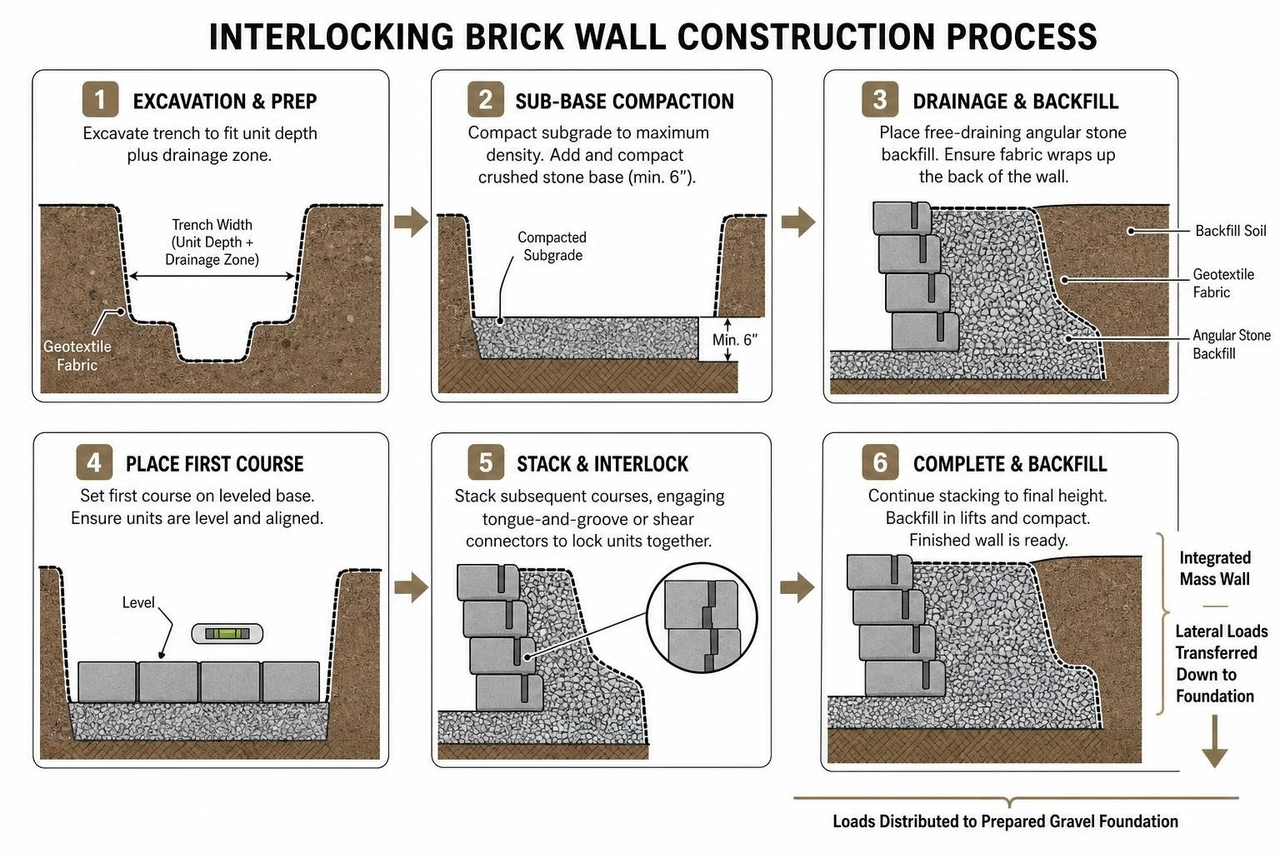
The installation begins with trench excavation sized to accommodate the unit depth plus an expansive stone drainage zone. Trench depth must equal a minimum of 6 inches of compacted aggregate base plus the required unit embedment depth below finished grade. On level ground, base unit embedment is calculated as wall height divided by 20 (minimum 6 inches buried), with deeper embedment mandated for sloped toe conditions.
- Sub-Base Compaction: The excavated subgrade is compacted using heavy reversible vibratory plate rammers to achieve maximum density before lining the trench with geotextile fabric.
- Base Material Placement: A 6-inch minimum foundation footing of clean, open-graded crushed stone (such as AASHTO No. 57 aggregate) is placed and screeded level side-to-side and front-to-back.
- Drainage Pipe Integration: A 4-inch perforated collection pipe is set directly behind the base course on a slight positive grade, routed to daylight beyond the wall returns or connected to an approved shoreline discharge outlet.
- Aggregate Backfill: Clean angular crushed stone is placed behind the block face to a minimum depth of 12 inches, creating an open drainage corridor that prevents moisture accumulation as detailed in our guide to constructing a retaining wall with blocks.
Best Practices in Interlocking Brick Wall Construction Techniques
Every course above the foundation dictates the ultimate plumb, alignment, and stability of the retention system. When executing how to construct a brick retaining wall at a professional marine grade, certified crews stack units in a running bond pattern, offsetting vertical seams by at least one-third to one-half of the block length.
Rear-lip blocks or glass-filled polymer pins are inserted into pre-molded unit slots to automatically establish an exact 3/4-inch setback per course (a 5-degree batter angle). Units are pulled firmly forward against the pin stops or rear lips to lock the alignment before backfilling. Masons align the blocks using the rear shell rather than the split-face profile to avoid line drift caused by architectural face texturing. Top capstones are secured to the underlying course with double beads of high-strength, flexible polyurethane construction adhesive, meeting all technical specifications for segmental retaining walls.
Geogrid Integration and Structural Tiering
When an earth retention structure exceeds 3 feet in height or retains steep backslopes, mechanical soil reinforcement becomes essential. High-tenacity biaxial geogrids are embedded between block courses and extended horizontally into the reinforced backfill zone behind the wall.
- Placement and Tensioning: Geogrid layers are rolled out perpendicular to the wall face, pulled taut to eliminate wrinkles, and anchored into place before soil spreading.
- Lift Compaction Protocols: Granular backfill is spread over the geogrid in 6- to 8-inch lifts and consolidated using walk-behind vibratory plate compactors. Heavy machinery is strictly operated beyond a 3-foot buffer zone from the wall face to avoid outward displacement.
- Tiered Wall Geometry: For multi-tiered systems, the upper wall must be set back at a distance at least double the height of the lower wall (2H). If placed closer, the upper tier acts as a structural surcharge, requiring extended geogrid embedment lengths and custom load-bearing calculations.
Site Evaluation, Long Island Coastal Durability, and Maintenance
Coastal and waterfront properties across Long Island face severe environmental exposure, including salt spray, shifting water tables, and saturated soil loads. In communities like Southampton, Westhampton, West Islip, and Brightwaters, retaining systems must withstand coastal soil movement. Our team builds long island retaining walls designed specifically to handle these demanding coastal conditions.
Routine maintenance for interlocking commercial retaining systems involves keeping the subsurface drainage pathways unobstructed. Annual assessments should verify that perforated drain outlets remain clear of marine silt and debris, capstones stay securely adhered, and backfill grades continue shedding surface runoff away from the retaining structure rather than ponding behind the wall face.
Long Island Coastal Soil Retention and Structural Engineering
Retaining soil near coastal waterways, canals, and bays requires specialized engineering to prevent toe erosion and structural scour. When building waterfront retaining walls, the transition zone between the upland grade and the active tidal line demands heavy geotextile-wrapped stone backfill matrices and riprap toe armor to resist tidal wash.
Navigating structural requirements across Nassau and Suffolk Counties requires deep familiarity with coastal geotechnical factors and shoreline conditions. From projects in Massapequa, Wantagh, Bellmore, and Merrick to structural bulkheading in Bayshore, Babylon, Cold Spring Harbor, Huntington, and Lloyd Harbor, site-specific engineering is vital. Pearce Marine Construction stands out as the superior choice over competitors like Bayview Dockbuilders and Kevel through unmatched local coastal expertise, meticulous craftsmanship, and dedicated structural precision. To schedule a comprehensive engineering evaluation for your shoreline protection or soil retention structure, connect directly with our team through our bulkhead and seawall contracting services.



Bring Your Vision to Life
Whether you're planning a custom dock, seawall, or boat lift, our experienced team is ready to deliver high-quality marine construction tailored to your needs. Pearce Marine Construction brings craftsmanship, precision, and a deep understanding of Florida’s waterways to every project. Let us help you create a durable, beautiful solution that stands the test of time. Get in touch now for a personalized estimate!